
 Jane and John's RV pages
TV Sound Modification for variable low-level audio output
Objective:
Provide a variable low-level TV sound output at the appropriate signal level to drive an external audio amplifier
Background:
Winnebago Industries uses an external amplifier (QSurround) that supposedly can mimic 5.1 surround sound from a two channel input (left/right audio) by driving several speakers. As configured for our 2005 Itasca Horizon 40AD, the QSurround will accept inputs from the dash radio or the TV and outputs to five cube speakers and one woofer located by the driver's position. Never have I been able to detect any unique sound ambience properties, but maybe I didn't listen carefully enough. (Another project was to install a 'real' Dolby Digital 5.1 home entertainment amplifier, but I digress)
Requirements:
Skills - you should have good soldering skills and be comfortable working with small electronic components (plumbing soldering skills aren't going to cut the mustard here.) If the thought of taking the back off of your $1,000 TV scares you, this is not a good thing, find an electronics geek that can help
Parts & tools - electronic tools (small side cutters, needle nose pliers, low wattage pencil tip soldering iron), appropriate screwdriver to remove the back of the TV, rosin core solder, shielded wire, RCA type female phone plugs (or whatever you need), and four low wattage resistors (see the picture of the resistor package for the values.) Wattage isn't critical - I used 1/2 watt for ease of handling, but you could use 1/4 watt or 1 watt - doesn't matter
Other:
The arrangement of the resistors is important for best performance, so please note the resistor color code in the following pictures. Give some thought to where the two shielded wires will exit the TV cabinet and provide strain relief and a long enough cable that will make replacing the back of the TV easy and of course enough cable on the outside of the TV to reach your destination.
Disclaimer:
Legal stuff: While I have attempted to provide the most accurate directions and instructions, you assume all of the risk if you attempt the same procedure and process. Your results aren't guaranteed. Perform your due diligence before attempting this modification and satisfy yourself you that have the appropriate skill level, tools and parts to proceed. If you disassemble your TV or make modifications to it, be advised that activity might immediately void any warranty on the TV
Let's get going!
We are assuming you have figured out how to gain access to your TV's speakers - I can't help with that!

Here we are ready for the operation - figuring out which screws to remove was quite the challenge!

Close up of a 'virgin' speaker. Note the speakers have polarity, black wire I'm assuming is the ground side. Wire the modification with the shield side of the cable to the ground side of the speaker

Obviously from Rat Shack. There are also on-line sources - Jameco is a good one. Google for a link to them
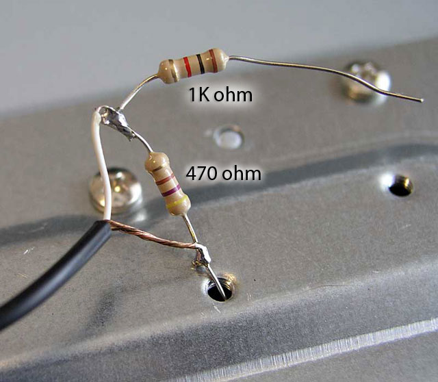
Make up your resistor bridge first, it makes installation much easier. Pay attention to the resistor color code I have here and duplicate. Again, the cable shield side will go the speaker negative or ground side

Here we have soldered the resistor/cable assembly to the speaker leads

Provide strain relief for the cables

Arrows point to the new cable - notice the cable ties. Surgery complete and ready to close 'er up!
-End-